Our Process
We begin a project by taking notes of the client's brief, preparing base drawings of the existing site, and studying the relevant bye-laws. Before any real design starts, we typically create an area programme that is derived from the client's brief and some basic room sizes. The total resultant area is often more than can actually be built. The brief and area programme is discussed and rationalised into something that is more likely to fit within the building envelope.
Once the area programme makes sense, it is time to start laying out rough room shapes into the outline of the allowed building envelope. When the client is happy with the room locations, the room shapes are enclosed with walls. Furniture is inserted into the layouts so that we can see how the rooms can be used, how one will be able to walk around, where it makes sense to place doors, and so on. Our design process is evolutionary. We don't produce three complete designs and ask the client to pick one. The design evolves with the client's input at every step. It evolves from a sketchy plan to a properly worked-out plan to an entity that one can properly visualise in three dimensions.
The images below show examples of the drawings that we produce during the course of a typical project. Click on an image to see a larger version, where you can zoom in to see the details.
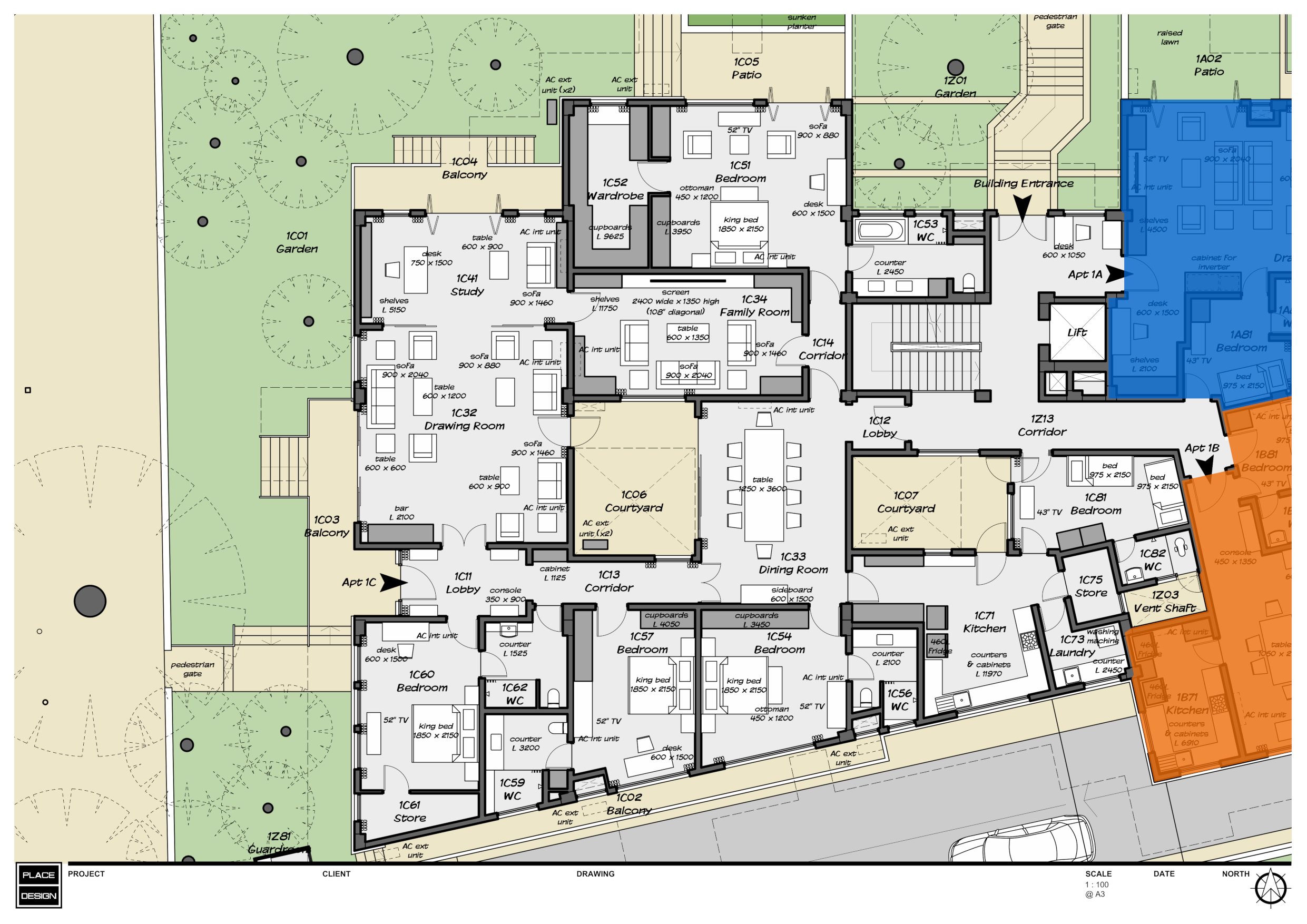
A design plan shows the layout of the building. We can see the location and size of rooms, as well as how they relate to adjacent spaces. Doors, windows and furniture give a good idea of how the spaces are likely to be used, and give good visual scale of how much space there is to move around. The scale of this drawing would typically be 1:100.
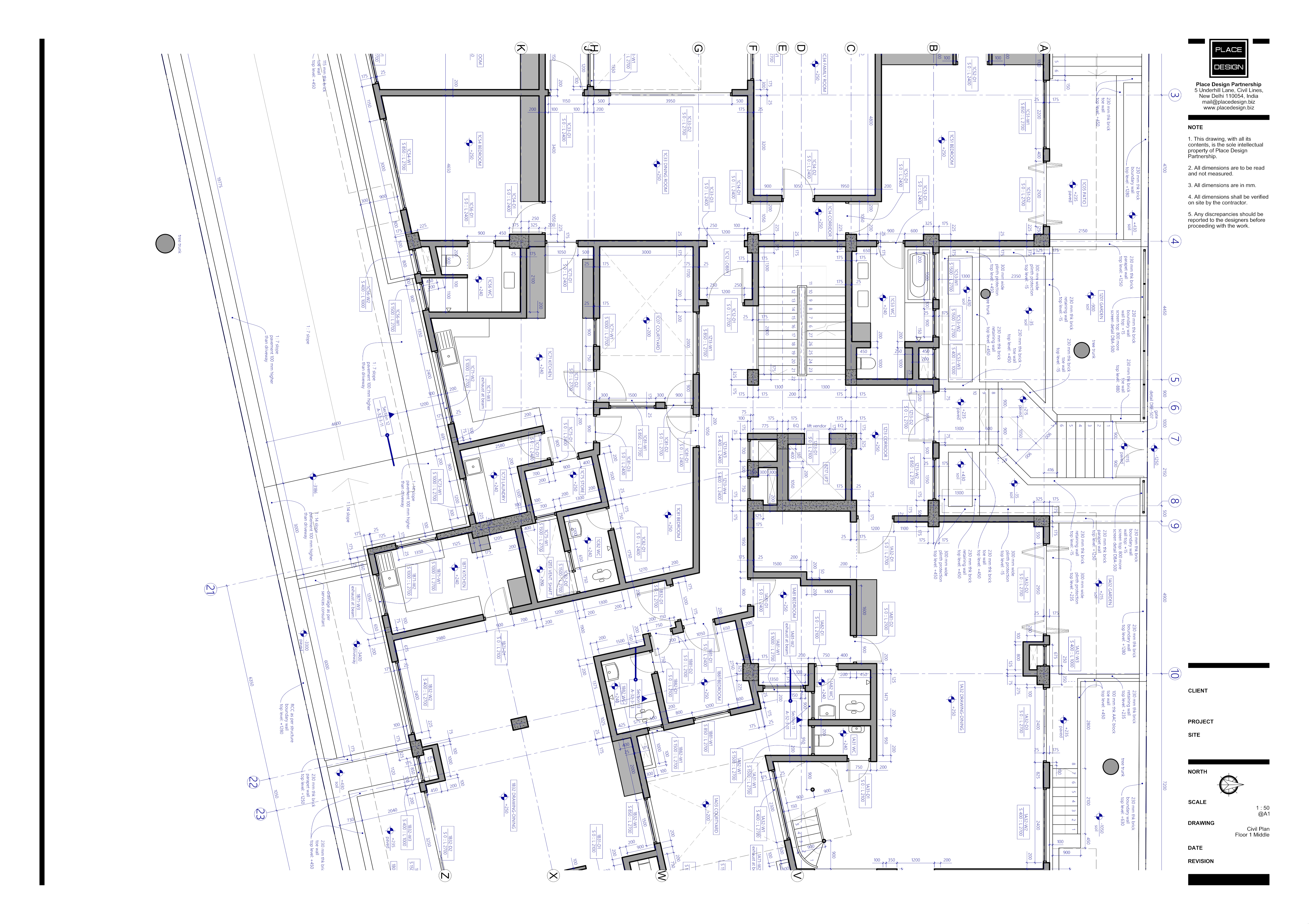
The civil plan is the starting point of the working drawings. Most other drawings are based on these in some way or another. This works hand-in-hand with the structural engineer's drawings. Together, they show the contractor exactly how to lay out the brick and concrete, which is the primary part of the building. The scale of this drawing would typically be 1:50.
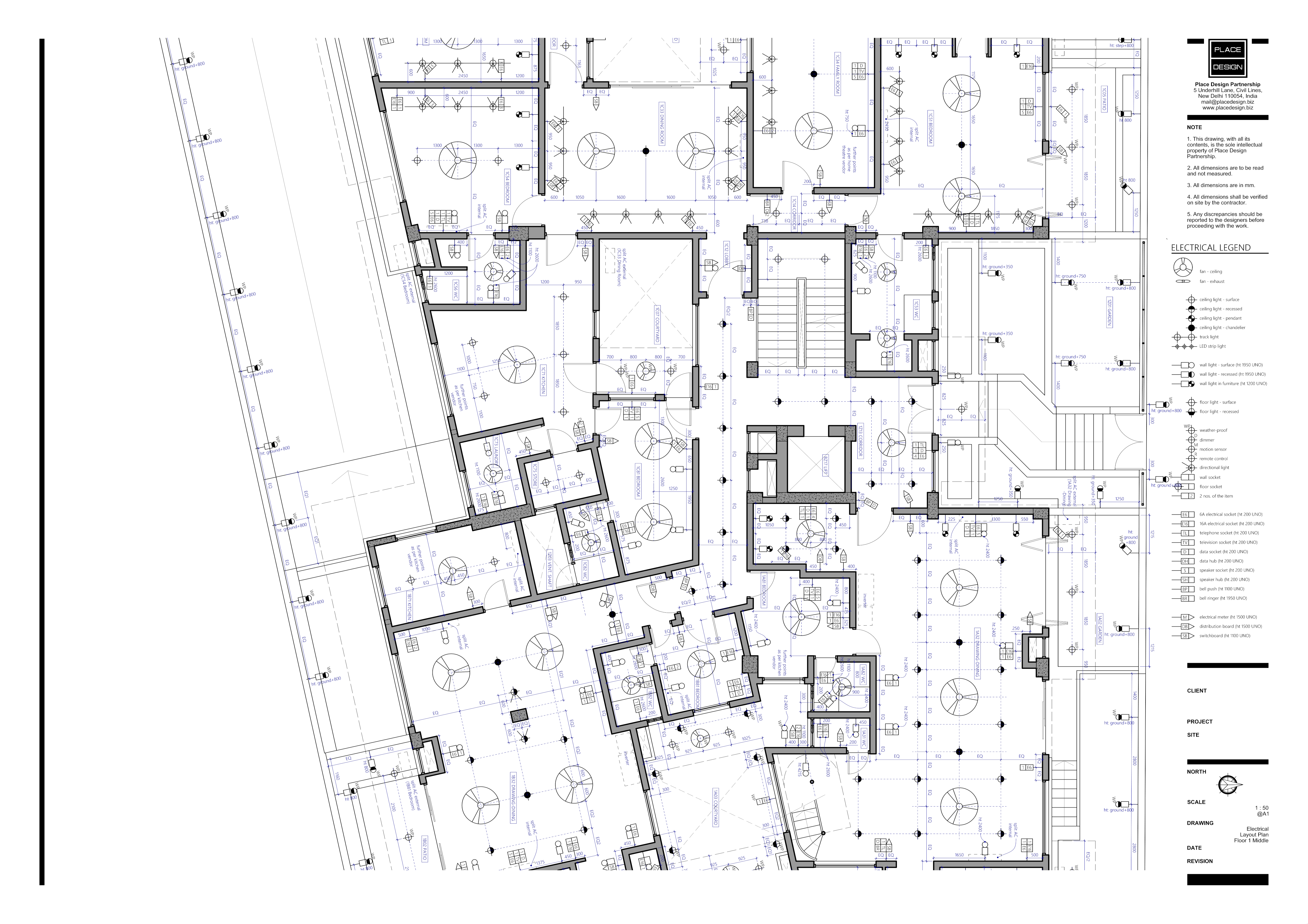
The electrical layout plan shows the location of every light, fan, air-conditioner, switchboard and socket in the building. Locations are decided by the furniture layout and how the client would like to use each space. The scale of this drawing would typically be 1:50.
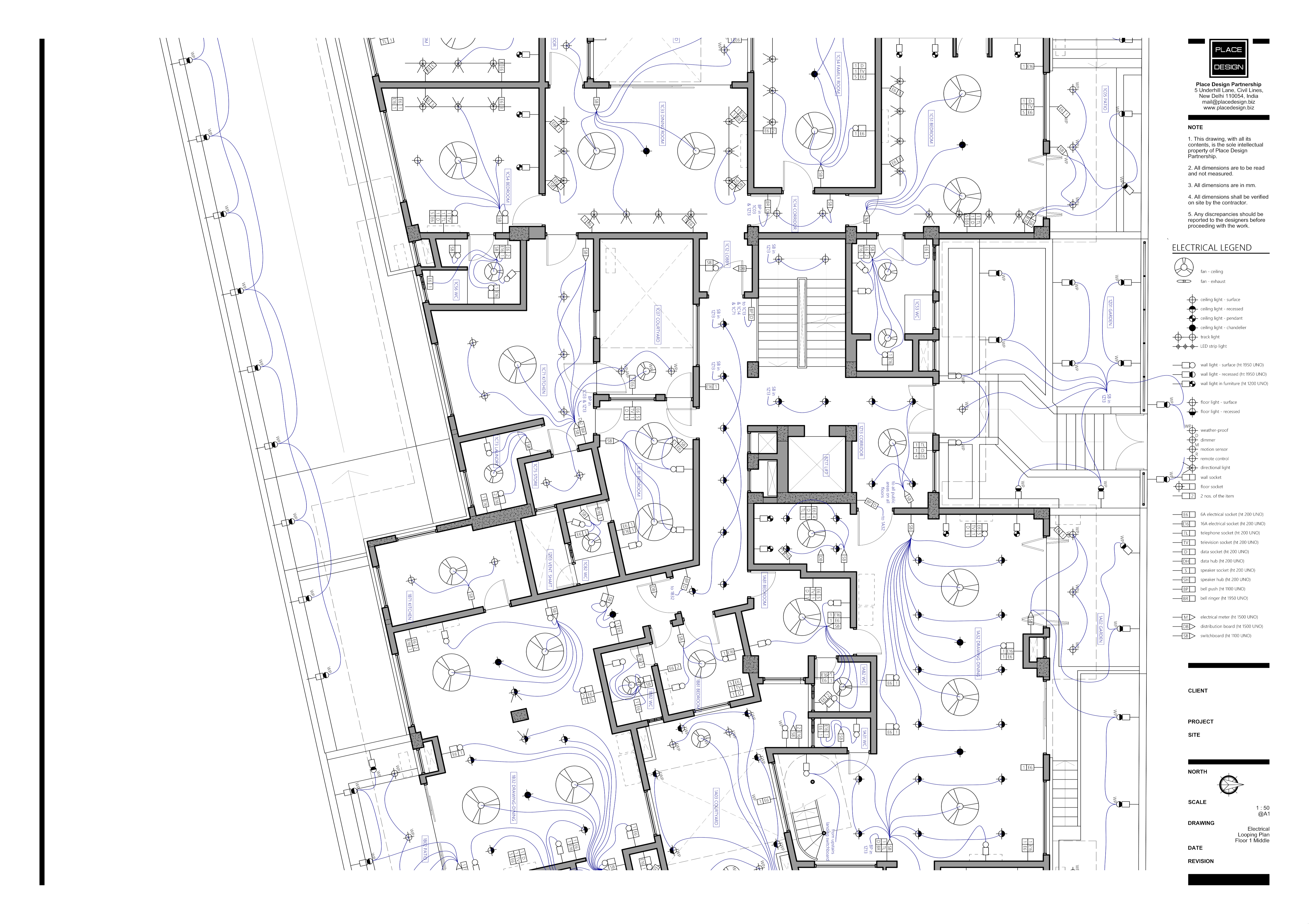
The electrical looping plan shows how each switchboard is connected to lights, fans and so on. It also shows how some lights are switched on using the same switch. The scale of this drawing would typically be 1:50.

The opening schedule describes every door and window opening in the building. Each opening is numbered on the civil plan. The schedule provides further detail of each one. This is useful both for the team who constructs the civil work, as well as the team that produces the doors and windows that fit into the openings.
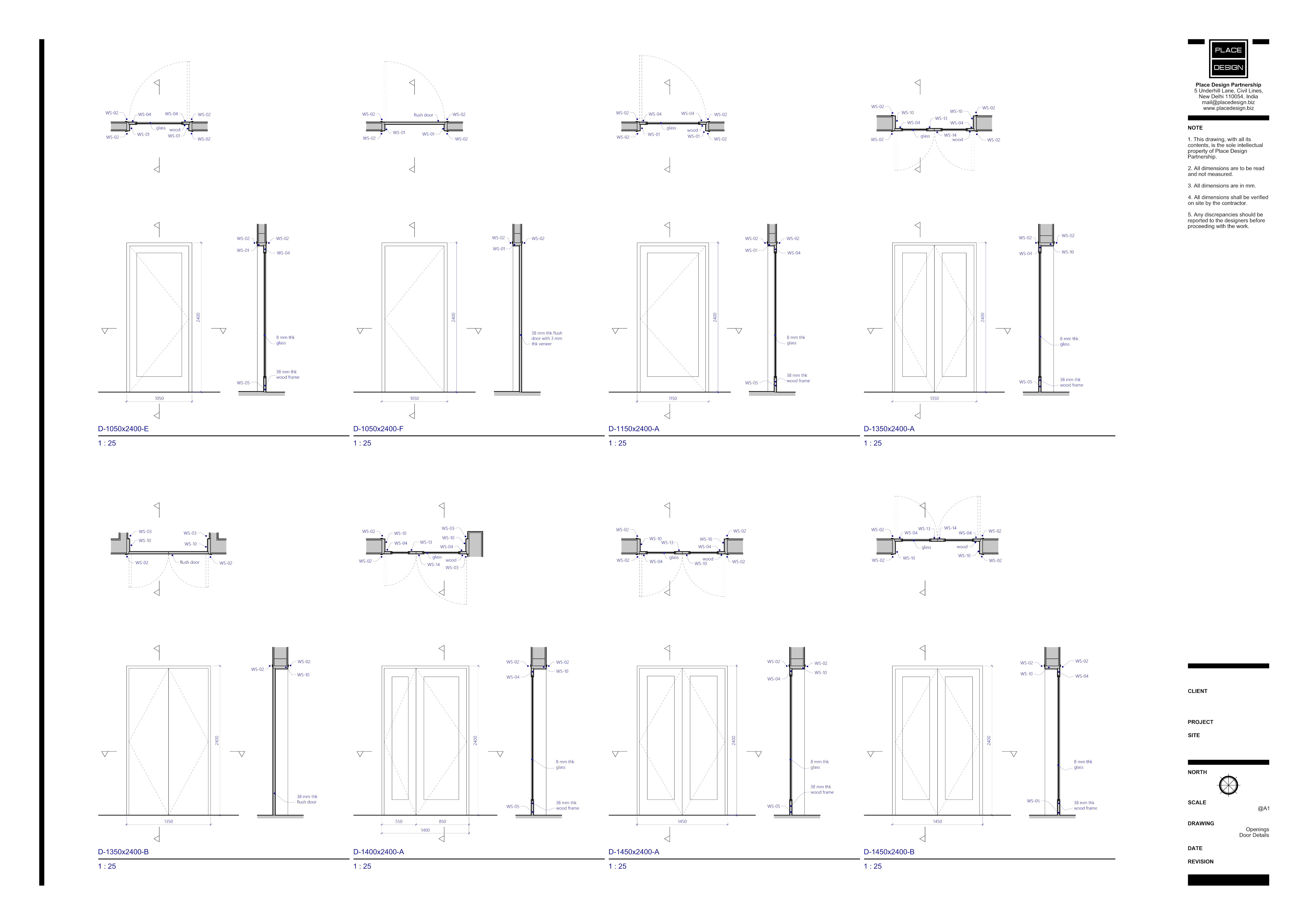
Door and window details describe these items that will fit into the civil openings. How they open, whether they swing, slide or are fixed. How many shutters, and the size of each. The scale of this drawing would typically be 1:25.

Architectural details describe some items that are typical to many parts of the building, as well as some that are specific to a single location. They are mainly about how the building is put together and how to achieve the exterior aesthetic that has been designed. Items might include boundary walls, exterior railings and parapets, the relationship between wall, slab, waterproofing, floor finish and so on. The scale of these drawings would typically be between 1:25 and 1:2.
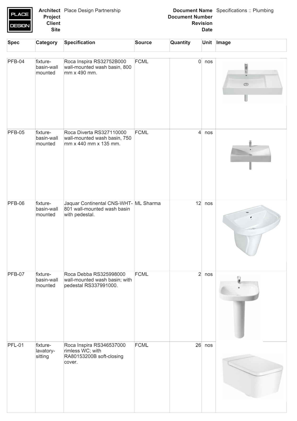
Plumbing specifications are a list of plumbing items, including basins, toilets, taps and towel rails, that have been selected by the client and architect. Each item is given a code for easy reference, and a suggestion of where one might buy it. An image is usually included for every item so that there is no confusion about what has been selected. Similar specifications are prepared for electrical items like lights and fans, as well as finish materials like tile and stone.
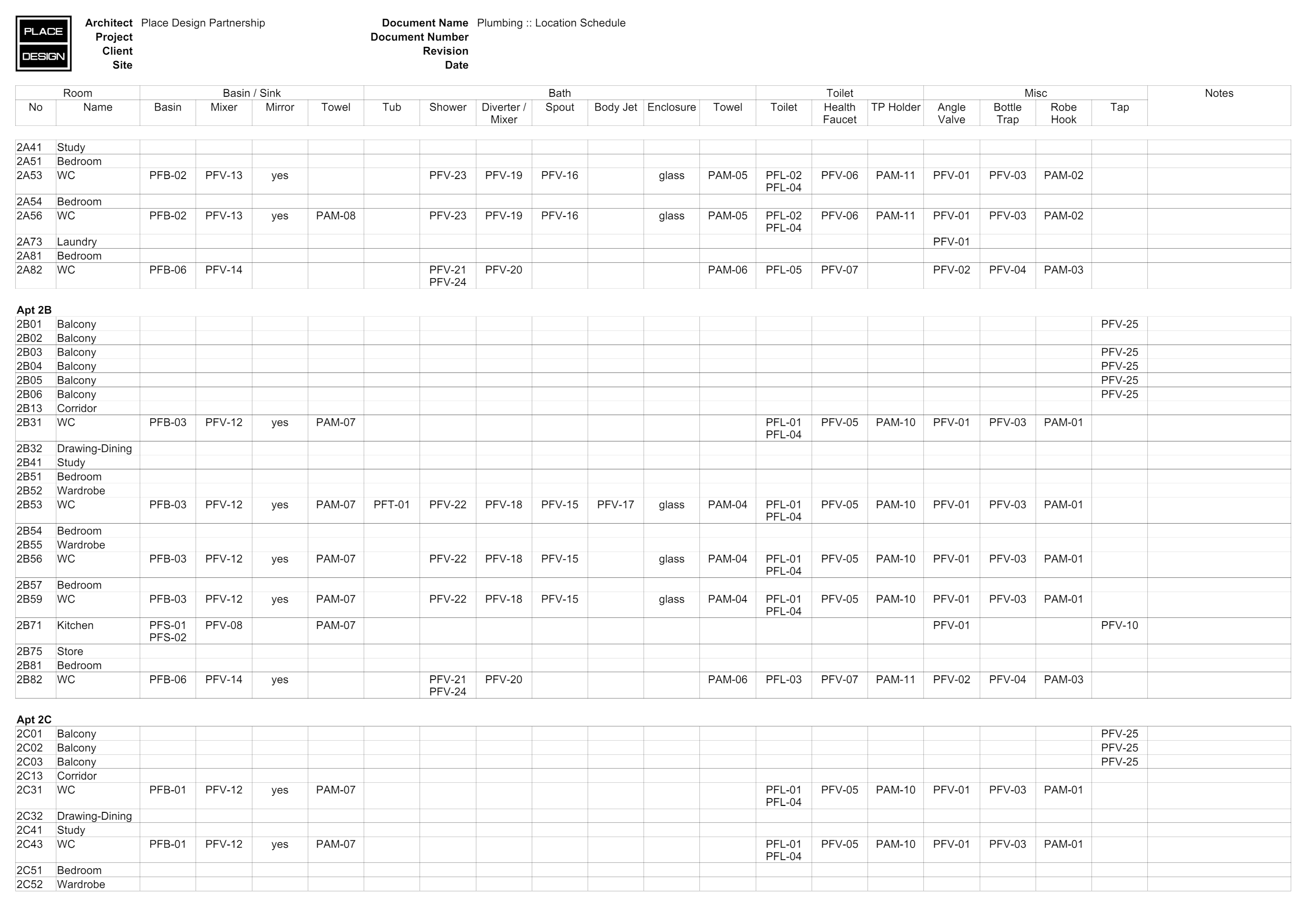
The plumbing location schedule refers to the plumbing specifications and shows where each item will be used. It is a useful way of seeing how each space will be fitted out. Similar schedules are prepared for electrical items and finish materials.
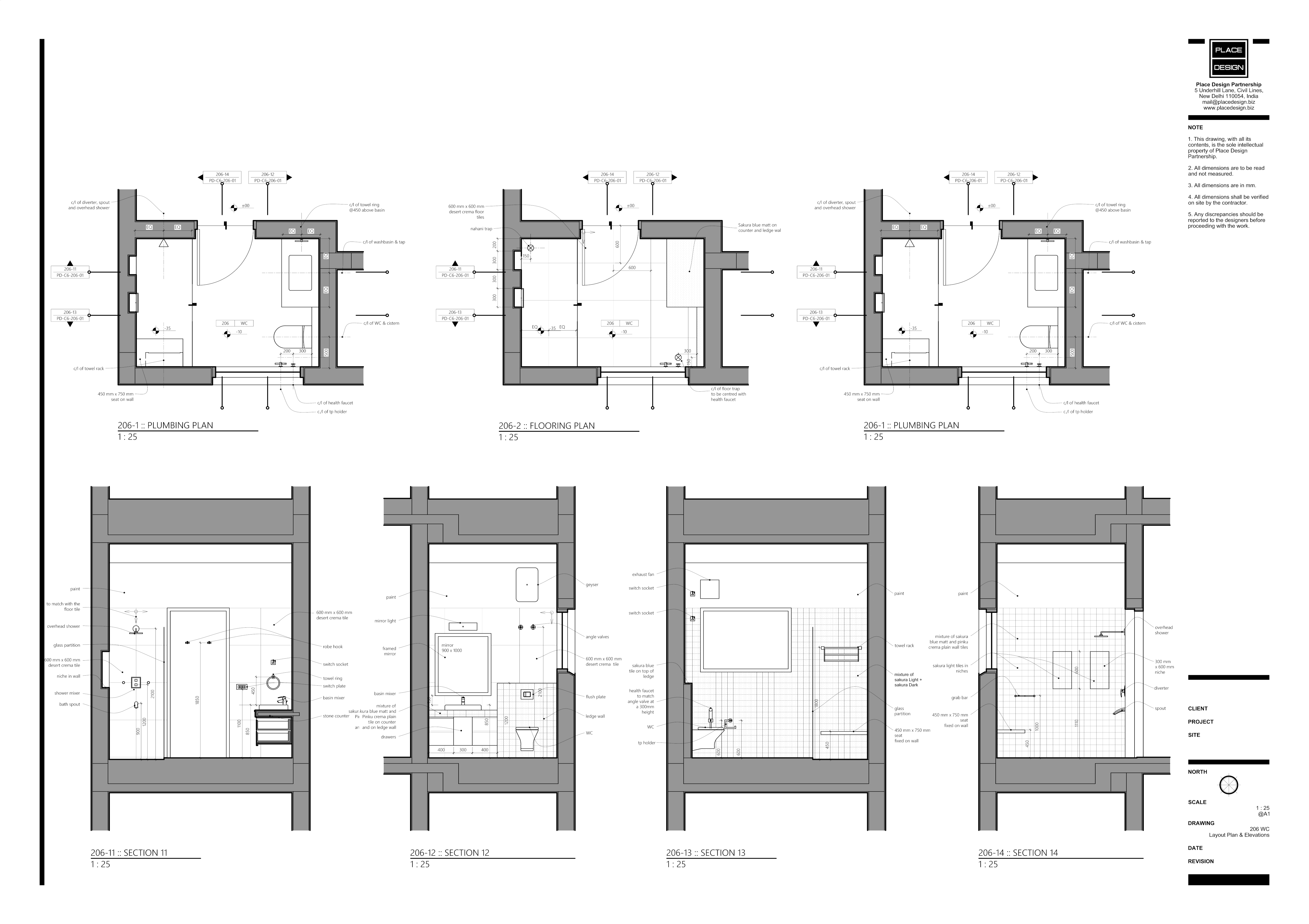
Bathrooms are spaces that typically require a lot of attention to detail, and these drawings show it. The scale of these drawings would typically be 1:25.
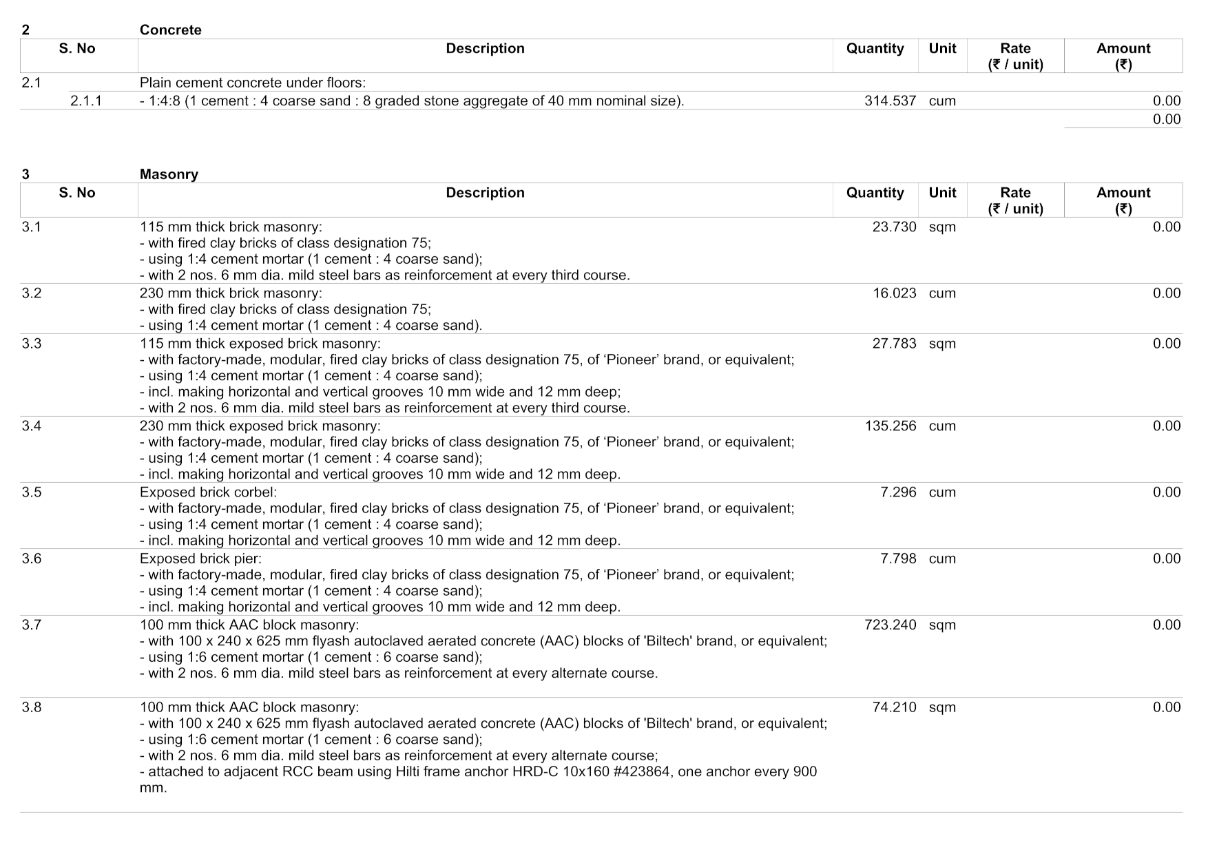
Long before construction begins, the client will want to know how much the whole thing will cost. At the beginning of the project, all we really know is how many square feet we are likely to build. Using the thumb rule of square foot rate, we estimate a project cost. This is very tentative. When the design is complete and the bulk of the working drawings are done, we put a lot of effort into calculating the quantity of each building material. This is assembled into the bill of quantities, a page of which is shown here. The working drawings and the bill of quantities are given to bidding contractors, who then have a very clear idea of what they need to build. They can provide a construction cost based on the very personalised needs of the client. At this stage, items such as basins, taps, lights, fans, stone and tiles have usually not been selected, and therefore the contractors' quotes will not include them. These can strongly influence the final cost. So we quantify these items, make a reasonable assumption about the products that might be selected, and complete the cost estimate. That way, the client has a fairly good idea of the final cost before the project breaks ground.